AC fixed metal-clad switchgear")
Overview
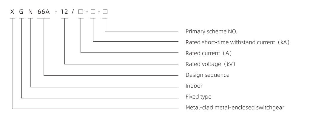
XGN66-12 AC Fixed Metal-clad Switchgear is a new generation of high-voltage electrical complete set products. It complies with the national standard GB3906 “10-35KV AC Metal-Enclosed Switchgear” and the power industry standard DLT404-1997 “Technical Conditions for Indoor AC High-Voltage Switchgear Orders.” It also meets the international standard IEC62271-200 ” AC Metal-Enclosed Switchgear and Control Equipment Above 1kV and Below 52kV.” It has the “five-prevention” interlocking function.
This product absorbs advanced foreign technology and is designed and developed to address the high accident rate and large volume issues of similar existing switchgear in operation in China. It has the advantages of small size, occupying only 50% of the volume of ordinary switchgear. The circuit breaker is reliable and has good performance, and the “five-prevention” interlocking mechanism is reliable and simple.
Model meaning
Ambient Condition
Ambient Air Humidity: Upper limit +40°C, lower limit -10°C.
Altitude: Maximum installation altitude of the equipment is 1000m.
Temperature: Daily average relative humidity not exceeding 95%,monthly average relative temperature not exceeding 90%.
Seismic: Seismic intensity not exceeding 8 degrees
Surrounding air should not be significantly polluted by corrosive or combustible gases, steam, etc.
No severe pollution and frequent severe vibration in the area.
Main technical parameters of vacuum circuit breaker
| Main technical parameters and components of switchgear | |||
| Serial number | Projects | Unit | Technical parameters |
| 1 | Rated voltage | kV | 3.6,7.2,12 |
| 2 | Rated power frequency withstand voltage | kV | To the ground, interphase :42: fracture :48 |
| 3 | Rated lightning impulse withstand voltage | kV | To the ground, interphase :75: fracture :85 |
| 4 | Rated frequency | Hz | 50 |
| 5 | Rated current | A | 630,1250, |
| 6 | Rated short-circuit breaking current (effective) | kA | 20,25,31.5, |
| 7 | Rated short-circuit closing current (peak) | kA | 50,63,80, |
| 8 | Rated dynamic steady current (peak) | kA | 50,63,80 |
| 9 | 4 s (Valid) Rated Thermal Stability Current | kA | 20,25,31.5 |
| 10 | Protection level | IP2X | |
| 11 | Shape dimensions (width x depth X height) | mm | 900x1000x2300 |
| 12 | Weight | kg | ≈ 600 |
Main Technical Parameters of QCE1-12 Type Vacuum Circuit Breaker
| Serial number | Projects | Unit | Technical parameters |
| 1 | Rated voltage | kV | 12 |
| 2 | Rated current | A | 630 1250 |
| 3 | Rated short circuit switching current | kA | 20,25,31.5 |
| 4 | Rated short-circuit closing current | kA | 50,63,80 |
| 5 | rated short-time withstand current (4 s effective) | kA | 20,25,31.5 |
| 6 | Rated peak tolerance current (peak) | kA | 50,63,80 |
| 7 | Mechanical life | Third | 10000 |
| 8 | Rated short-circuit breaking current breaking | Third | 50 |
| 9 | I page of Rated Operations | s–0.3 and 180 | |
| 10 | Contact opening | mm | 11±1 |
| 11 | Contact stroke | mm | 4±0.5 |
| 12 | Interphase central distance | mm | 210 |
| 13 | Opening speed | m/s | 1.2±0.2 |
| 14 | Closing speed | m/s | 0.6±0.2 |
| 15 | Opening Time | ms | ≤60 |
| 16 | Closing Time | ms | ≤ 75 |
| 17 | Simultaneous Phase of Three-phase Switching | ms | ≤ 2 |
| 18 | Bounce on closing | ms | ≤ 2 |
| 19 | Circuit resistance | ≤ 45 | |
| 20 | Cumulative allowable wear thickness of contacts | mm | 3 |
the technical parameters of other electrical components see their respective instructions.
The scheme of ◊ switchgear rated current greater than 1600 A shall be settled in consultation with our company.
Installation
installation foundation refer to the following figure, the foundation channel steel protruding ground 1-3 mm, within a meter range of unevenness should not exceed 1.5 mm, within the full length range of not more than 5 mm..
place the switchgear on the basis of sequence, adjust the position of installation. Then use M12 bolts or spot welding method to fix, cabinet and cabinet with M8 bolts and tight. After disassembly, the cover plate is installed with main bus and primary cable, and the terminal contact surface should be cleaned and coated with neutral vaseline. Plug the cable hole once after installation.
connection cabinet indirect ground bus, so that along the direction of the switchgear arrangement into one, check whether there are omissions in working grounding and protection grounding, grounding circuit is continuous conduction, working grounding resistance should not be more than 1000 m Q, protection grounding resistance should not be more than 4 Q..
install the secondary cable, the cable is introduced by the front bottom of the cabinet, and the side wall enters the low voltage chamber, which is connected to the terminal row separately; or the low voltage chamber is introduced from the secondary small busbar on the top of the cabinet, and the cable hole is plugged after installation.
clean up the dust and debris in the cabinet.
Operation
Before the is put into operation, the following inspection and commissioning shall be carried out:
check whether the type and specification of the electrical components installed in the cabinet are in accordance with the order requirements; check whether the fasteners are loose; check whether the first or second wiring is correct; operate the isolating switch, grounding switch, circuit breaker, mechanical interlock 3~5 times, should be flexible jam phenomenon, interlock meet the “five prevention” requirements, and then add grease to the mechanical active parts.
check the insulation level of switchgear and circuit resistance, mechanical characteristics of circuit breaker according to article 3 of this specification and factory test report, the test results should be consistent with or similar to the factory test report.
Maintenance and repair
users should maintain and overhaul the switchgear regularly.
cleaning of all parts of dust, especially the surface of insulation dust;
check the moving parts of machinery, add grease regularly to keep it flexible and reliable.
circuit breaker, isolation switch, grounding switch and other components maintenance according to their respective instructions;
check whether the electrical contact part is good, whether there is overheating phenomenon, grounding circuit is on;
check regularly whether the fasteners are fastened.
the user should generally with the assistance of the manufacturer to carry out troubleshooting, in case of minor adjustments and minor failures, the user’s self-repair should refer to this specification and the main components of the respective specifications.
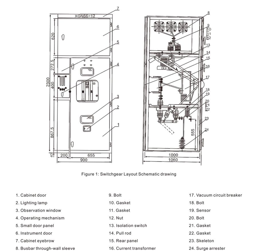
Schematic diagram of switchgear layout