KYN28A-12 3 Phase Power Distrbuting Combined Switchgear Cabinet, suitable for three-phase AC The 50Hz power system is used to receive and distribute electrical energy and control, protect and monitor the circuit.
This product conforms to the standard: GB3906 “3.6-40.5KV AC metal-enclosed switchgear and control equipment”, GB /T11022 “High-voltage switchgear Common technical requirements for equipment and control equipment standards”, IEC60298 “AC metal-enclosed switchgear and control equipment with rated voltage above 1KV and below 52KV “Preparation”, DL/T404 “Technical Conditions for Ordering Indoor AC High Voltage Switchgear”.
KYN28A-12 3 Phase Power Distrbuting Combined Switchgear Cabinet (hereinafter referred to as “switching device”), suitable for three-phase AC The 50Hz power system is used to receive and distribute electrical energy and control, protect and monitor the circuit.
This product conforms to the standard: GB3906 “3.6-40.5KV AC metal-enclosed switchgear and control equipment”, GB /T11022 “High-voltage switchgear Common technical requirements for equipment and control equipment standards”, IEC60298 “AC metal-enclosed switchgear and control equipment with rated voltage above 1KV and below 52KV “Preparation”, DL/T404 “Technical Conditions for Ordering Indoor AC High Voltage Switchgear”.
Technical parameters
| Project | Unit | Data | ||
| Rated voltage | KV | 3.6、7.2、12 | ||
| Rated frequency | Hz | 50 | ||
| Circuit breaker rated current | A | 630、1250、1600、2000、2500、3150、4000 | ||
| Rated current of switchgear | A | 630、1250、1600、2000、2500、3150、4000 | ||
| Rated short-time withstand current (4s) | KA | 16、20、25、31.5、40、50 | ||
| Rated peak withstand current (peak value) | KA | 40、50、63、80、100、25 | ||
| Rated short-circuit breaking current | KA | 16、20、25、31.5、40、50 | ||
| Rated short-circuit making current (peak value) | KA | 40、50、63、80、100、25 | ||
| Rated insulation level | 1 min power frequency withstand voltage | Between poles, between poles to ground | KV | 24、32、42 |
| Fracture | KV | 24、32、48 | ||
| Lightning impulse withstand voltage(peak value) | Between poles, between poles to ground | KV | 40、60、75 | |
| Fracture | KV | 46、70、85 | ||
| Protection level | The shell is IP4X, and when the door of the next door and circuit breaker room is opened, it is IP3X | |||
Note: 1. The short-circuit capacity of the current transformer is considered separately;
2. The technical parameters of ZN63A-12 are detailed in the corresponding samples of our company.
Product structure characteristics
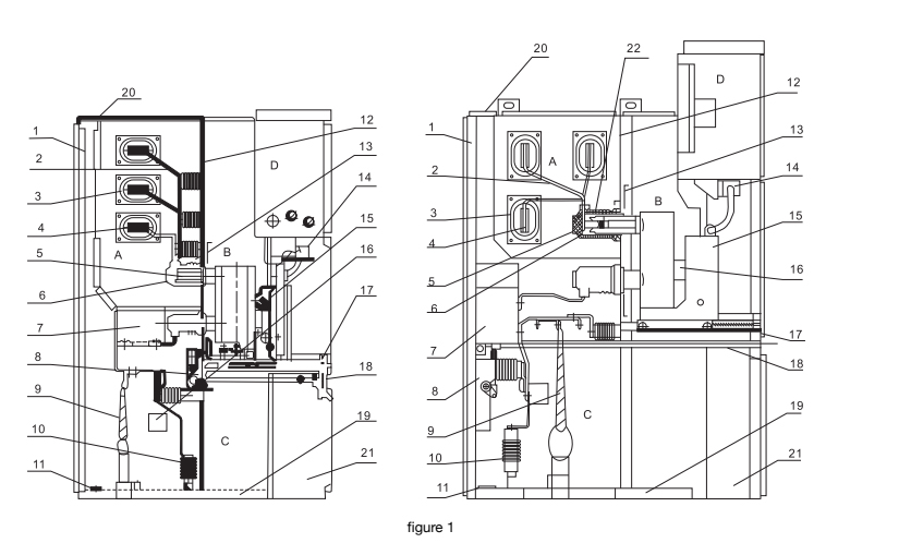
Switchgear structure (see Figure 1).
2. Completely metal armored, assembled structure, wide combination scheme.
3. The cabinet body is made of imported aluminum-zinc coated thin steel plate, processed by MINGE machine tool, and adopts advanced multifolding technology, connected with rivet nuts and high-strength bolts, and has high precision and light weight. High strength, strong versatility of parts.
4. It can be equipped with VS1-12 series or imported VD4 series vacuum circuit breakers, with wide applicability, high reliability, and long-term maintenance-free.
5. The handcart is equipped with working and testing positions, and each position has positioning and display devices, which is safe and reliable.
6. All kinds of handcarts are changed according to modular building blocks to ensure that cars of the same specification can be freely interchanged, and cars of different specifications are absolutely not allowed to enter.
7. Earthing switch installation method: (1) Installed in the middle of the cabinet (front-mounted) to facilitate double-sided maintenance after the cabinet (Figure 1-a). (2) Installed at the back of the cabinet (rear-mounted) to save space and area against the wall (Figure 1-b).
8. Current transformer installation method: (1) The cable room at the rear of the cabinet is installed in the front; (2) The large bent plate is hoisted at the bottom.
9. Up to 9 single-core cables can be installed in the cable room.
10. Each high-pressure chamber has a pressure relief channel to ensure personal safety.
11. The highly reliable interlocking device fully meets the “five prevention” safety requirements.
12. The handcart is transported by a special carrier, which is easy to operate and flexible.
13. The front and rear doors are equipped with observation windows, which can facilitate the observation of the working status of the indoor components

Technical parameters
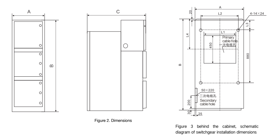
| Height B | 2300(2200) | |
| Height A | Rated current of branch small busbar ≤1250A, thermal stability current 40KA | 800(650) |
| Rated current of branch small busbar ≥1600A | 1000 | |
| Height C | Cable in and out | 1500 |
| Overhead incoming and outgoing lines | 1660 |

Dimensions
| (mm)Table 3(mm) | |||||
| Cabinet width A | Cabinet depth B | L1 | L2 | L3 | L4 |
| 800 | 1500 cable | 530 | 630 | 150 | 490 |
| 1660 overhead | 530 | 630 | 310 | 650 | |
| 1000 | 1500 cable | 730 | 830 | 150 | 490 |
| 1660 overhead | 730 | 830 | 310 | 650 | |