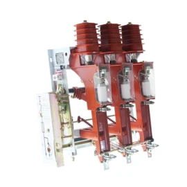
36/40.5kv Medium Voltage Vacuum Circuit Breaker with Modular
1.Overview:
1.1 Suitable for three-phase AC 50Hz, 35kV power system for switching various loads of different natures, and for occasions with frequent operations.
1.2 For the protection and control of electrical equipment used in industrial and mining, enterprises, power plants and substations.
1.3 Suitable for KYN61-40.5 handcart type switchgear.
1.4 Standard
GB/T 1984 High-voltage alternating-current circuit-breakers
GB/T 11022 Common specifications for high-voltage switchgear and controlgear standard DL/T 402 High-voltage alternating-current circuit-breakers
2.Technical Parameters:
| No. | Name | Unit | Value | |
| 1 | Rated voltage | kV | 40.5 | |
| 2 | Rated lightning impulse withstand voltage (peak) | 185 | ||
| 3 | 1 minute power frequency withstand voltage | 95 | ||
| 4 | Rated frequency | Hz | 50 | |
| 5 | Rated short-circuit breaking current | kA | 25 | 31.5 |
| 6 | Rated current | A | 630A ~ 2500A | |
| 7 | Rated short-time withstand current | kA | 25 | 31.5 |
| 8 | Rated peak withstand current | 63 | 80 | |
| 9 | Rated short-circuit making current (peak) | kA | 63 | 80 |
| 10 | 1 minute power frequency withstand voltage of the secondary circuit | V | 2000 | |
| 11 | Rated operation sequence | O-0.3s-CO-180s-CO | ||
| 12 | Rated short circuit duration | s | 4 | |
| 13 | Rated capacitor bank breaking current | A | 630 | |
| 15 | Mechanical life | times | 10,000 | |
| 16 | Rated short-circuit breaking current ON/OFF times | 20 | ||
| 17 | Allowable cumulative wear thickness of moving and fixed contacts | mm | 3 | |
| 18 | Rated closing and opening operating voltage | V | AC220/110, DC220/110 | |
| No. | Name | Unit | Value |
| 19 | Clearance between open contacts, overtravel | mm | Clearance 18±1 Overtravel 5±1 |
| 21 | Contact closing bounce time | ms | ≤ 3 |
| 22 | Three-phase closing and opening synchronization | ≤ 2 | |
| 23 | Average opening speed | m/s | 1.8±0.2 |
| 24 | Average closing speed | 0.8±0.2 | |
| 25 | Closing time | ms | ≤ 100 |
| 26 | Opening time | 20 ~ 50 | |
| 27 | Main circuit resistance | μΩ | ≤ 80( ≤ 1600A), ≤ 60( ≥ 2000A) |
| 28 | Rebound amplitude of breaking contact | mm | ≤ 2 |
3.Operating Conditions:
3.1 The ambient air temperature does not exceed +40℃, and the mean value measured within 24h does not exceed 35℃, and the min. ambient air temperature is -15℃;
3.2 Altitude: ≤1,000 meters.
3.3 There is no obvious pollutions such as dust, smoke, corrosion or flammable gas, steam gas, or salt spray in the ambient air.
3.4 Humidity conditions: The daily mean is not greater than 95%, and the monthly mean is not greater than 90%; the mean value of water steam pressure is not greater than 2.2KPa, and the monthly mean of water steam pressure is not greater than 1.8KPa;
3.5 Vibration or earthquake from the outside of the switchgear or controlgear can be omitted;
3.6 The magnitude of the electromagnetic interference induced in the secondary system does not exceed 1.6kV.
3.7 Special working conditions
If installed at the place where the altitude exceeds 1,000 meters, the ambient air temperature is out of the limit value specified by the normal working conditions or condensation may easily occur due to high humidity, please contact our company for customization.
4.Structure And Working Principle:
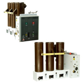
4.1 Reliable modular spring operating mechanism
The spring operating mechanism of circuit breaker is up-down arranged with manual and electric energy storage functions. With small size, the circuit breaker has high overall rigidity and consistent operating performance providing high stable operation.
4.2 Main conductive circuit is of the solid-sealed type
Main conductive circuit of circuit breaker is of the solid-sealed structure. The vacuum arc extinguish chamber and conductive parts of the primary main conductive circuit are overall solid-sealed in the pole through the advanced APG integrated forming process, suitable for various severe weather conditions. By fully considering the requirements of the harsh working conditions, this insulation structure is designed not only to prevent the influence of the external environment on the conductive circuit but also to prevent dust and foreign matters from entering main circuit. Furthermore, there is high resistance for voltage effect even in the damp-heat and severe dirty environment.
4.3 Standard breaking and closing function module
The circuit breaker is characterized by use of modular spring operating mechanism for convenient maintenance, fast replacement, and short power outage time for inspection. In addition, as the modular mechanism used as spare part has been lubricated with special grease and well-adjusted with a long storage period, no adjustment is required for replacement of the entire mechanism without changing the dynamic property of circuit breaker, minimizing the maintenance and inspection workload during operation. The failed modular structure can also be as spare part after repair and maintenance by the manufacturer.
4.4 Excellent handcart interchangeability and adaptation
The external dimensions of circuit breaker are basically consistent with those from the peer manufacturer, so that their handcarts can be interchanged conveniently for strong adaption and wide application. The circuit breaker is of the floor-mounted handcart type structure for convenient field inspection and regular maintenance by user without transferring handcart, suitable for KYN61-40.5 high-voltage complete switchgear.
5.Outline and Installation Dimensions:
VTG-40.5 Outline and installation dimensions

6.Electrical Schematic Diagram:
Electrical principle of interior of circuit breaker. The figure below shows the circuit breaker at the discharged and opening status