Understanding Active, Reactive, and Apparent Power
Electrical power is a fundamental concept in electrical engineering, governing the transmission and utilization of energy in AC circuits. To ensure efficient system performance, it is essential to understand the three key types of power: active power, reactive power, and apparent power. This article provides an in-depth exploration of these power components, their formulas, and their significance in electrical systems.
Active Power (P): The Usable Energy
Active power, also known as real power, represents the actual power consumed by electrical devices to perform useful work, such as generating heat, light, or mechanical motion. It is measured in watts (W) and signifies the energy directly utilized by the system.
The formula for active power is:
P=V×I×cos(θ)P = V \times I \times \cos(\theta)
Where:
- P = Active power (W)
- V = RMS voltage (V)
- I = RMS current (A)
- cos(θ) = Power factor, representing the phase difference between voltage and current
Active power is the essential component that enables electrical equipment to function effectively. It is the power produced by generators, batteries, and other power sources.
Reactive Power (Q): The Power That Supports Voltage Stability
Unlike active power, reactive power does not perform any actual work but is necessary for maintaining voltage levels in an AC circuit. It arises due to the presence of inductive and capacitive elements, such as motors, transformers, and capacitors, which cause energy to oscillate between the source and the load. Reactive power is measured in volt-amperes reactive (VAR).
The formula for reactive power is:
Q=V×I×sin(θ)Q = V \times I \times \sin(\theta)
Where:
- Q = Reactive power (VAR)
- V = RMS voltage (V)
- I = RMS current (A)
- sin(θ) = Phase angle between voltage and current
Although reactive power does not contribute to useful work, it plays a crucial role in power system stability. However, excessive reactive power can lead to inefficiencies, increasing current flow and power losses.
Apparent Power (S): The Total Power Flow
Apparent power represents the total power supplied to a system, combining both active and reactive power. It is measured in volt-amperes (VA) or kilovolt-amperes (kVA) and determines the total power demand in an AC circuit.
The formula for apparent power is:
S=V×IS = V \times I
Where:
- S = Apparent power (VA)
- V = RMS voltage (V)
- I = RMS current (A)
Apparent power defines the required capacity of electrical components, such as transformers, generators, and transmission lines, to handle total system demand effectively.
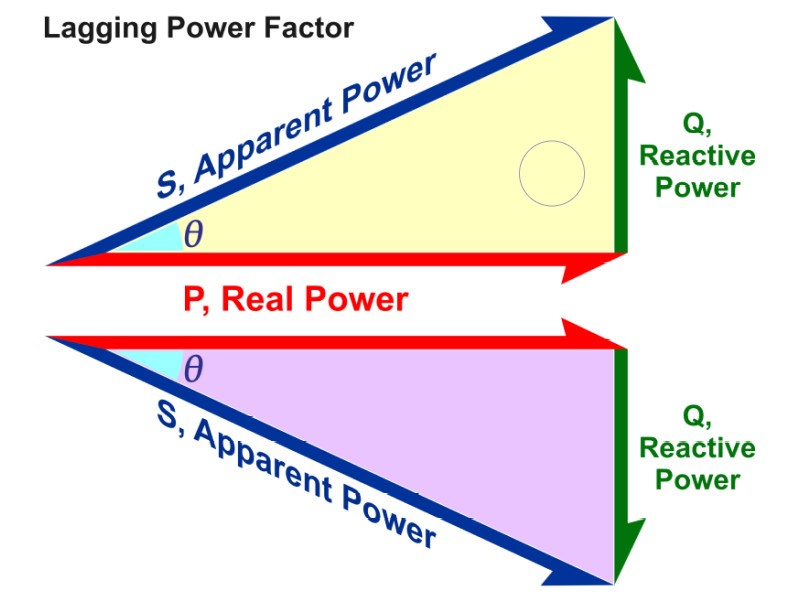
Relationship Between Active, Reactive, and Apparent Power
These three power components are interrelated through the power triangle, which follows the Pythagorean theorem:
S2=P2+Q2S^2 = P^2 + Q^2
Where:
- S = Apparent power
- P = Active power
- Q = Reactive power
This equation highlights that the apparent power is always greater than or equal to the active power, with reactive power influencing the overall power demand in the system.
Power Factor: A Measure of Efficiency
The power factor (PF) indicates the efficiency of power usage in a circuit. It is the ratio of active power to apparent power, expressed as:
Power Factor=PS=cos(θ)\text{Power Factor} = \frac{P}{S} = \cos(\theta)
A power factor closer to 1 (unity) signifies higher efficiency, meaning most of the apparent power is converted into useful work. Conversely, a low power factor indicates excessive reactive power, leading to inefficiencies and increased energy costs.
Importance of Reactive Power Management
Although reactive power is essential for voltage regulation, excessive amounts can cause:
✅ Increased current flow, leading to higher energy losses
✅ Voltage instability, affecting equipment performance
✅ Reduced energy efficiency, requiring more power to maintain system functionality
To improve power factor and minimize losses, industries use power factor correction techniques, such as:
⚡ Capacitor banks – Neutralize inductive loads by providing leading reactive power
⚡ Synchronous condensers – Adjust reactive power flow to optimize voltage stability
⚡ Static VAR compensators (SVCs) – Dynamic control of reactive power for efficient energy management
Applications and Practical Implications
Understanding active, reactive, and apparent power is crucial for various electrical applications, including:
🔹 Power Transmission & Distribution – Ensuring efficient energy transfer and reducing losses
🔹 Motor & Generator Design – Proper sizing and selection of electrical machines
🔹 Energy Efficiency Optimization – Improving power factor to reduce operational costs
🔹 Electrical System Design – Determining transformer, switchgear, and conductor ratings
🔹 Power Quality Improvement – Minimizing voltage fluctuations and extending equipment lifespan
By effectively managing power components, engineers can enhance system performance, reduce costs, and improve overall energy efficiency.
Conclusion
A solid understanding of active, reactive, and apparent power is essential for optimizing electrical systems. By maintaining a high power factor and minimizing unnecessary reactive power, industries can achieve:
✔ Higher efficiency
✔ Lower energy costs
✔ Improved power quality
✔ Enhanced reliability of electrical networks
As technology advances, mastering these power concepts will remain a key skill for electrical engineers and professionals. Proper power management will continue to drive sustainable and efficient energy solutions for the future. 🚀
Professional Switchgear supplier and manufacturer
- Zhejiang GONGSHUN Electrical Co.,Ltd (electricgs.com), Our company was founded in the late 1990s, specializing in the production of inflatable cabinets, SF6 inflatable cabinets, and various high and low voltage complete sets of electrical equipment. It has multiple subsidiaries under its jurisdiction, including high-voltage load switch branch, high-voltage circuit breaker branch, high-voltage fuse branch, and technology development branch.Our technical expertise, comprehensive product portfolio and long-term rich experience are helping many customers in need to solve their power problems. We’re happy to help at any time. Whether you need application product advice or technical assistance, our global service team is committed to providing you with the right support. For more technical information about medium voltage earthing switch, feel free to contact us, send an email to gongshun@electric-cn.com
- Our company specializes in producing 12KV-40.5KV series high-voltage electrical products: FZN58, FLN48, FLN36, FZRN25, FZN21, FN18, ZFN16, FN12, FN8, FN7, FN5, XRNT, XRNP, VS1, ZN28, ZW8, ZW32, JN15, GN19, GN22, GN24, GN30, CLXGN15-12, HXGN □ -12, DXG-12 (L), DFW □ -12 high-voltage cable branch box, CLXGN □ -12 (SF6) series inflatable cabinet 12KV and 35KV cable accessories, etc; CLVXP-12 indoor AC high voltage fixed switchgear, CL-SIS-12 compact solid insulated ring main unit, professional assembly Schneider SC6 (SF6) series load switchgear, ABB produced SFG (SF6) series load switchgear and other series products; Distribution and agency of high-voltage load switches and inflatable cabinets produced by Schneider Electric and ABB; Siemens produces the 3AJ1 series of indoor medium voltage vacuum circuit breakers and other related products. The company has a complete range of products and has been operating safely on domestic and international power grids for a long time, receiving unanimous praise from both new and old users. Among them, multiple products such as FZRN25, FN12, FLN36-12, XRNT-12 have been exported to various countries and regions in East Asia, South Asia, Southeast Asia, Africa, and the United States.